Components Automotive
Air Conditioning
Compressors
Air Conditioning
Compressors
parti 2
Rotary vane compressors consist of a rotor with three or four vanes and a carefully shaped
rotor housing. As the compressor shaft rotates, the vanes and housing form chambers.
The R134a is drawn through the suction port into these chambers, which become smaller as
the rotor turns. The discharge port is located at the point where the gas is fully compressed.
The vanes are sealed against the rotor housing by centrifugal force and lubricating oil. The
oil sump and oil pump are located on the discharge side, so that the high pressure forces oil
through the oil pump and then onto the base of the vanes keeping them sealed against the
rotor housing.
During idle an occasional vane noise from the compressor may be heard. This is due to the
time taken for lubricating oil to circulate through the A/C system.
Manufactured of either plate, cast iron, steel or aluminium, this bracket should exhibit
excellent noise absorption qualities especially if using a piston type compressor.
Idler Pulley
A small pulley normally used in conjunction with a belt adjusting mechanism, also used when
a belt has a long distance between pulleys to absorb belt vibrations.
Drive Pulley
Some vehicles do not have an extra pulley to accommodate an A/C drive belt, in these
cases an extra pulley is bolted onto the existing crankshaft pulley.
Lubrication:
R134a is part of the air conditioners lubrication system. NEVER operate an A/C system
without refrigerant as there will be no lubrication for the compressor and internal damage will
occur.
Refrigerant oil is circulated around the A/C system saturated in the refrigerant.
Ariazone recomends PAOil as best automotive compressor lubricant.
PAOil is a Polyalpha Olefin, Not a PAG or an Ester. This is a fully synthetic oil,
carefully blended to be a superior oil. It is so good that it can be used in all
automotive compressors, whatever the brand. It's a non-agressive, safe oil
that won't effect seals or hoses and is compatible with other lubricants.
And it's non-hygroscopic.
Rotary Vane - Panasonic:
Rotary vane compressors consist of a rotor with three or four vanes and a carefully shaped
rotor housing. As the compressor shaft rotates, the vanes and housing form chambers.
The R134a is drawn through the suction port into these chambers, which become smaller as
the rotor turns. The discharge port is located at the point where the gas is fully compressed.
The vanes are sealed against the rotor housing by centrifugal force and lubricating oil. The
oil sump and oil pump are located on the discharge side, so that the high pressure forces oil
through the oil pump and then onto the base of the vanes keeping them sealed against the
rotor housing.
During idle an occasional vane noise from the compressor may be heard. This is due to the
time taken for lubricating oil to circulate through the A/C system.
Compressors and Mount & Drive:
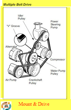
Mount & Drive
Consists of a bracket to mount the compressor to the engine, a belt idler pulley, compressor
drive belt and possibly and extra drive pulley for the crankshaft.
Compressor Mount
Mount & Drive
Consists of a bracket to mount the compressor to the engine, a belt idler pulley, compressor
drive belt and possibly and extra drive pulley for the crankshaft.
Compressor Mount
Manufactured of either plate, cast iron, steel or aluminium, this bracket should exhibit
excellent noise absorption qualities especially if using a piston type compressor.
Idler Pulley
A small pulley normally used in conjunction with a belt adjusting mechanism, also used when
a belt has a long distance between pulleys to absorb belt vibrations.
Drive Pulley
Some vehicles do not have an extra pulley to accommodate an A/C drive belt, in these
cases an extra pulley is bolted onto the existing crankshaft pulley.
Clutches:
Compressor Clutch
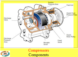
The clutch is designed to connect the rotor pulley to the compressor input shaft when the field coil is energized. The clutch is used to transmit the power from the engine crankshaft to the
compressor by means of a drive belt. When the clutch is not engaged the compressor shaft does not rotate and refrigerant does not circulate the rotor pulley free wheels. The field coil is actually an electromagnet, once energized it draws the pressure plate towards it, locking the
rotor pulley and the pressure plate together causing the compressor internals to turn, creating
pressure and circulating refrigerant.
Lubrication:
R134a is part of the air conditioners lubrication system. NEVER operate an A/C system
without refrigerant as there will be no lubrication for the compressor and internal damage will
occur.
Refrigerant oil is circulated around the A/C system saturated in the refrigerant.
Ariazone recomends PAOil as best automotive compressor lubricant.
PAOil is a Polyalpha Olefin, Not a PAG or an Ester. This is a fully synthetic oil,
carefully blended to be a superior oil. It is so good that it can be used in all
automotive compressors, whatever the brand. It's a non-agressive, safe oil
that won't effect seals or hoses and is compatible with other lubricants.
And it's non-hygroscopic.
Precautions when using PAG oil::
- Do not allow PAG oil to contact bare skin or vehicle paintwork.
- Flush skin immediately when using PAG oil.
- Avoid breathing PAG oil/R135a mixture.
- PAG oil is highly hygroscopic. Open containers only when ready to use. Cap container
immediately after use.
- Do not allow PAG oil to contact bare skin or vehicle paintwork.
- Flush skin immediately when using PAG oil.
- Avoid breathing PAG oil/R135a mixture.
- PAG oil is highly hygroscopic. Open containers only when ready to use. Cap container
immediately after use.
kandi younes
abo bahaaeddine


